Start with an airport and its surroundings
Choose Layered in the studio, find a US airport, and frame the surrounding area in Map. Denver is a useful first Class B project; Colorado Springs (COS) is a useful Class C project. A wider crop shows the changing shelf footprints; a tight crop around a runway may sit entirely inside one sector and produce a single plate.
Open the Aviation panel and turn on Airspace in 3D. This builds acrylic above the terrain. The switches above it, under On the map, draw airport and airspace linework instead; they do not turn on the acrylic model.
FAA coverage includes the US and its territories. Only the selected Class B, C, D and special use sectors are modeled. The default Crater Lake crop may have no selected airspace. These are decorative models, not for navigation or flight planning.
Choose how to build the airspace
Under Build as, choose Layered for acrylic only at the altitudes where airspace starts or ends, with open air between levels, or Solid for acrylic sheets that fill each modeled sector from floor to ceiling. Solid uses several times the acrylic and weight.
Layered airspace asks what Each level holds:
| Each level | What you make | When to choose it |
|---|---|---|
| Whole slice | A piece cut to all the airspace at that altitude, with the shelves that start or end there frosted and the sectors it passes through engraved. | Sturdy pieces that overlap, so one rod can rise through several levels. Reads like a map of the airspace at each height. |
| Shelves only | Only the shelves that start or end at that altitude: the upside-down wedding cake of the chart users' guide. A sector that starts at the surface gets a floor just above the terrain. | The least acrylic and the clearest steps. Narrow rings need more rods of their own. |
The two look much alike over a single Class B, whose shelves share one ceiling. They differ most where special use areas span several levels: a whole slice shows such an area at every level it passes through, shelves only at its floor and ceiling.
Under Acrylic, choose Clear to cut every piece from clear acrylic, with each class shown by its engraved chart line style, or Chart colors to cut Class B and the prohibited, restricted and warning areas from blue acrylic and Class C, MOAs and alert areas from magenta. New airspace starts clear, and the acrylic stays as you set it when you change the form.
The pieces are clipped to your map frame. Class D is represented as a lid rather than a filled tower-airport volume. Where a Class C shelf or a special use area carries on through the lid's height, the lid stops at that airspace's edge, so overlapping areas never cut into each other.
Choose the classes and ceiling
Class B, Class C and Special use are on initially. Turn on Class D for tower-airport lids. At least one kind stays selected. Special use includes areas such as MOAs, restricted and warning areas; small fragments or areas outside your frame may produce no pieces.
Ceiling cap limits how high the model extends, in feet above mean sea level (MSL). The automatic cap uses the highest selected Class B or C ceiling in the crop, or 10,000 ft when there is none. An explicit cap can cut off a sector or exclude it entirely if its floor is above the cap. Use Cap at the highest Class B or C ceiling to return to automatic selection.
Charted MSL heights stay tied to sea level. Surface and AGL limits follow the terrain, with steps where the wooden sheets require them; flight levels are converted for the model. Unlimited sectors stop at the ceiling cap. Engraved annotations retain the original altitude reference where they fit.
Set the scale and acrylic
Airspace uses the terrain's Vertical exaggeration. Around a whole Class B airport, 10× is a useful starting point for separating shelves. A tight airport crop may already make the airspace very tall: widening the crop or lowering exaggeration reduces its physical height. Watch the reported height in the airspace settings.
Set Acrylic thickness to your measured stock and Acrylic kerf to your laser's cut width in acrylic. Their initial values follow the terrain material thickness and laser kerf. Rod size, fit clearance and socket depth control the supports; see cutting and assembling airspace before choosing them.
Generate and inspect both previews
- Select Generate terrain or Regenerate terrain after choosing the crop. Wait for generation to finish. Enabling airspace on generated terrain also updates its data and geometry.
- Choose 3D stack. Orbit the model to see each shelf and its supports. The airspace settings report pieces, levels, total height and rods.
- Choose Cut layers, then set Cut material to Airspace acrylic. Move the level slider to inspect cut outlines, sockets and engraved markings at each altitude. Choose Terrain sheets to inspect the wood and its rod sockets.
- Read the warnings. Closely spaced boundaries may merge onto one level; small or unsupported pieces may be omitted. A merged or simplified model should be compared with your intended design before cutting.
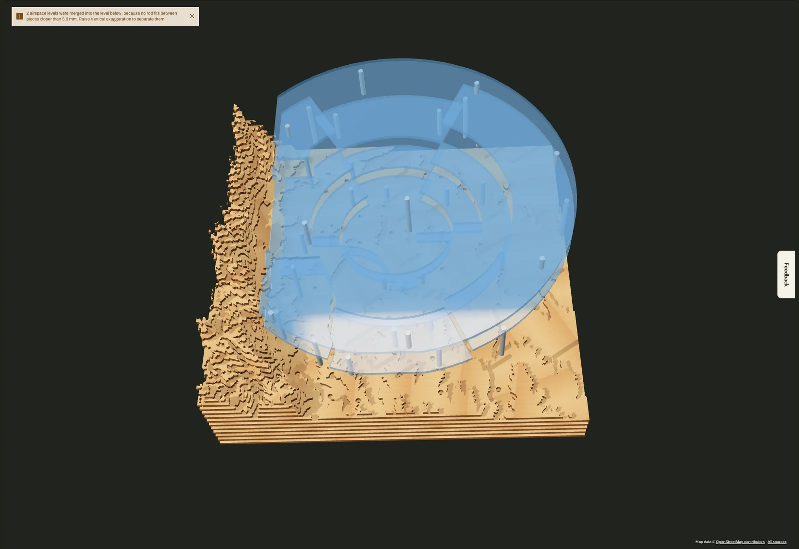
If the sky stays empty
Check the piece count in the airspace settings. With zero pieces, confirm that the crop includes a selected class, that the ceiling cap is above its floor, and that pieces are not being removed by terrain clearance or support constraints. Try a wider airport crop. Class E and G are not built by this feature.
If data is unavailable, regenerate after the connection recovers. After a data update, a hard refresh or a private window can help identify a cached archive. If pieces are listed but not visible, return to 3D stack and zoom out to include their height. For a reproducible report, use Copy share link or export your project settings. See airspace troubleshooting.
Export the model
Open Export and choose Airspace for its acrylic files, or Complete project for terrain and airspace together. The export includes the rod cut list and assembly instructions. Missing or incomplete requested data and stacks that exceed fabrication limits must be resolved before exporting. Continue with the airspace assembly guide.